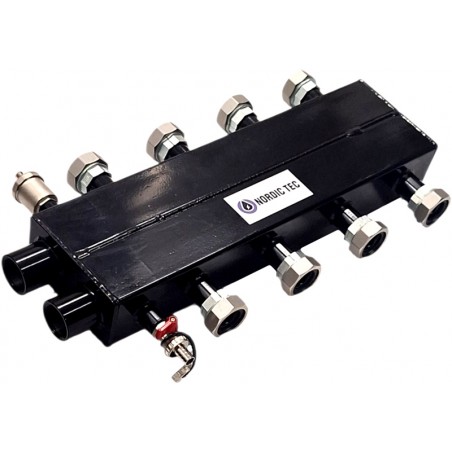
Connections of the 2+2 hydraulic separator–manifold
The connections of the 2+2 hydraulic separator–manifold differ in size depending on their function:
- main connections (90 mm spacing): 1 1/4” female thread
- main connections (125 mm spacing): 1 1/4” (with 1 1/2” female threaded union nut)
- for the air vent: 1/2” female thread
- for the drain valve: 1/2” female thread
✅ The spacing of the separator–manifold connections is standard, i.e. 125 mm. This is a distance considered standard and compatible with most pump groups, including Nordic Tec pump groups. It is also identical to other
manifolds typically used with pump groups.
__
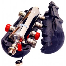
The device - 4 heating circuit low loss header combines the functions of a hydraulic separator and a central heating manifold, it is used in heating systems to connect installation zones with different temperatures / flows to one heat source. Similarly, it can also be used in cooling installations. The low loss header like this - highly advanced.
Principle of operation of a heat distributor-manifold with low loss header
Flow and pressure disturbances may occur in systems with a boiler circuit pump and, in addition, pumps for individual heating circuits. The manifold creates a low pressure drop zone in which the primary and secondary circuits are hydraulically separated. The flow in one of the circuits becomes independent of and no longer influences the flow in the other circuit. As a result, both circuits achieve the desired flow, which is generated by the pumps used, without excessive distortions.
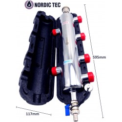
The manifold consists of a separator - big steel low loss header (primary circuit) and a compact manifold (secondary circuit) directly connected to the separator. After the supply (primary circuit) has been installed, the supply for the secondary circuits must be connected to the same manifold chamber. Crossover between supply and return should be strictly avoided .
The installation position of low loss headers 2+2 is free, horizontal or vertical, but horizontal connection is recommended as the vertical position makes it impossible to use air vents.
The ½ ”connections (2 pcs. near the main exits) are intended only and exclusively for the vent and drain valves. The heating circuits should definitely not be connected there.
CORRECT INSTALATION CAN ONLY BE DONE BY A QUALIFIED INSTALLER
Installation of the 2+2 hydraulic separator–manifold
The device consists of a manifold on the primary side and a parallel collector on the secondary side. The device can be installed in any position; however, horizontal installation is recommended, as it allows the use of an air vent and a drain valve.
The hydraulic separator–manifold should be connected in accordance with the flow diagram, which is also available in the product gallery. It is recommended to follow the principle of avoiding the crossing of supply and return flows of oppositely connected circuits or pump groups, as indicated by arrows in the diagram.
In practice, this means that once the primary connection for a circuit is selected, for example the upper connection, the supply lines of the secondary circuits on the opposite side must be connected in the same manner. Consequently, the return lines must also be connected correspondingly to each other, on the respective sides of the device body.
It should also be noted that the connections intended for the air vent and the drain valve (size 1/2") must under no circumstances be used to connect heating circuits. If the device is installed in a position that does not allow the installation of an air vent (e.g. vertical), these connections must be capped.